
Creating Geometries
In this tutorial we will create several geometries and use transformations to design a little street scene.
Subsection: Building a house
| User Activity | ||||||||||||||||||||||||||||||||||||||||||||||||||||||||||||||||||||||||||||||||||||||||||
|---|---|---|---|---|---|---|---|---|---|---|---|---|---|---|---|---|---|---|---|---|---|---|---|---|---|---|---|---|---|---|---|---|---|---|---|---|---|---|---|---|---|---|---|---|---|---|---|---|---|---|---|---|---|---|---|---|---|---|---|---|---|---|---|---|---|---|---|---|---|---|---|---|---|---|---|---|---|---|---|---|---|---|---|---|---|---|---|---|---|---|
|
||||||||||||||||||||||||||||||||||||||||||||||||||||||||||||||||||||||||||||||||||||||||||
What happens in detail is this: Since an Element Set
has already been created, we now need to edit the vertices. In order to
do that, make sure that the element set is the currently active
geometry. You can check what the active geometry is in the display
panel. In the main menu, you can open it via
--> or by clicking CTRL-d. At the bottom of that panel in the
"Geometries" section, you can select the active geometry by marking it
in the left list box. Now open the info panel through the main menu via
-->
--> or by pressing CTRL-i. This is where vertices and elements
can be edited. First we need to enter the number of vertices, that we
want as corners of the faces. Since we are going to build a square
house with a roof, we need a total of 9 vertices. Then you need to
enter every coordinate of each vertex. When entering the numbers from
the box above, press Enter after each input.
Next we need to construct the faces. Since we are building a house,
we need four walls, a floor and four roof elements. So enter 9 in the
text field named
in the info panel. For each element you now need to enter the indices
of those vertices, that shall be the corners of the face.
It is important, to enter the indices in the order in which they are
connected by the border of the face; otherwise, the face will look
degenerated. To help getting the vertices in right order, you can label
all vertices by their index. In order to do that you need to open the
material panel by either opening it in the main menu under -->
--> or pressing CTRL-m. Then simply enable the checkbox at the top of the
panel.
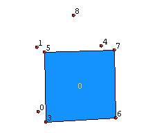
Correctly ordered vertices
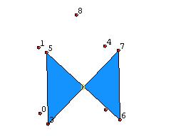
Incorrectly ordered vertices
| Summary | |
|---|---|
| Select active geometry | Open the display panel through the main menu, --> or CTRL-d and select the geometry in the list box. |
| Create vertices | In the main menu, --> --> or CTRL-i then increase the number of vertices by increasing the number in the corresponding text field and then edit the vertex coordinates in the text fields below. |
| Create faces | In the main menu, --> --> or CTRL-i, then increase the number of elements by increasing the number in the corresponding text field and then edit the indices in the text fields below, indices must be valid vertices in the above list. |
Building a Street
| User Activity | ||||||||||||||||||||
|---|---|---|---|---|---|---|---|---|---|---|---|---|---|---|---|---|---|---|---|---|
|
||||||||||||||||||||
We are now going add a small street to our little scene. We simply
do that by adding another Element Set and contructing one
face. First we need to create a new empty Element Set. In
order to do that open the main menu and go to
--> -->
and in the opened dialog, select
in the category list and
in the item list. Then add the element set by making sure that the radio box is selected and clicking the button.
Now we have created a new geometry. Open the info panel of that
geometry with CTRL-i or via the main
menu, make sure it is selected as the active geometry, by default an
newly created geometry is active. Now set up 4 vertices and 1 face. For
convenience you can use the values in the box above.
To differentiate the street from the house, the street should have a
different color. We can assign colors to faces, vertices and other
elements in the material panel, which you can reach in the main menu
via --> -->
or by pressing CTRL-m. To change the
face color, click on the current color to open the color selection
dialog or enter a color directly by RGB values into the appropriate
text fields.
| Summary | |
|---|---|
| Add new geometry | In the main menu, --> --> , select the desired geometry type, make sure the radio box is selected and click . |
| Change colors | In the main menu, --> --> or CTRL-m, then edit the RGB values or click on the currently selected color to open the color chooser dialog |
Building a City
| User Activity | |
|---|---|
|
|
Finally we can add more houses to our street. But instead of adding
an new element set, we are duplicating the already built house and move
the duplicate by transformation into another location.
To duplicate the house geometry, open the display panel either in the
main menu via --> or by pressing CTRL-d. Then click the
button and select the geometry, that represents our house. You will see
a new item in the list thats prefixed by the word "Clone", this is the
duplicat. At the moment you cannot see a new geometry, because the
duplicate is at the very same spot as the original. To move a geometry,
we are going to use transformations. Open the Transform dialog in the
main menu through --> --> . In this dialog, you have the possibilty to use the
three basic transformation scale, translate and rotate. For each
transformation type there are three sliders. Each slider represents one
axis. You can now move the duplicate house to a new location or scale
it to get a larger house or maybe a small doghouse. Below is a finished
sample street scene.
| Summary | |
|---|---|
| Duplicate geometry | In the main menu, --> , click the button and select the geometry to be dupliated |
| Transform geometry | In the main menu, --> --> , then use the sliders for each axis of each transformation type to apply scaling, translation or rotation to the geometry |