Part:
User Interface of
JavaView
Chapter: Inpectors
Section: Material Panels
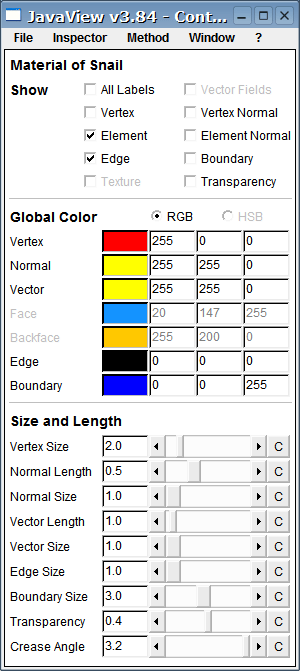
Subsection: Material Panels - Element Sets
Show
The labels of all vertices are shown all at one time. That can be a real mess if the point set is dense and you are looking from far away! But it is immense helpful sometimes.In case the point set has a vector field assigned to it's vertices it is shown as parts of straight lines. They can be made to small arrows by --> --> .
All vertices are hidden in case this checkbox is not selected. That will make the point set invisible if it is not a part of an element set or polygon or something else.
Shows/hides this particular vector field. Only available if vertex normals have been assigned to this point set.
All elements are hidden in case this checkbox is not selected. That will make the element set translucent. Edges or vertices of elements are shown if show-edges/vertices is selected.
Show/hide element normals. The element normals form a vector field that is based on the element midpoints. This option is only available if element normals has been assigned to this element set. To assign element normals to this element set use Method-Apply-MakeElementNormals.
If activated the edges of elements are emphasized by colored lines as given in color entries below.
If the elements set has a border (this is a question of connectivity) and this option is set the border is marked with a thick line.
If a texture image is assigned to this element set and texture coordinates has been set then this option makes it visible/invisible.
This will enable transparency for the elements. You can use the Transparency slider to change its value.
Global Color
Set specific colors. Click the left mouse button on the colored field to open a color dialog that allows you to pick a color by the mouse. You can also define the RGB values of the color directly at the text fields to the right of the colored field.Set the vertex color for all vertices of this geometry.
Set the colors of all normal vectors of this geometries.
Set the colors of all vectors of all assigned vertex based vector fields.
Sets the globally used color for element planes.
Sets the globally used color for element backplanes.
Set the color of element edges for all elements.
If the bounds of this geometry are shown this will be their color.
Size and Length
Sets the diameter in pixels of all vertices of this geometry.The length of the normals/vectors in world metrics (should be one) is multiplied with this double value before they are projected.
Width of the normals respectively vectors in pixels.
Sets the virtual thickness of the element edges in pixels.
Sets the virtual thickness of the borderline of this element set.
Sets the transparency of the elements where 0 is opaque and 1 is transparent. Checkbox "Show Transparancy" must be enabled to see the effect.
Determines when lighting and surface colors vary smoothly or discontinuously across face edges. If the angle between two faces is larger than the crease angle then the edge is a crease with discontinuity, otherwise (=default case) light and colors will smootly change. Only applies if "smooth lighting" or "smooth colors and local element colors" are effective.
Click into this applet and press Ctrl-m.